MicroBlocks
MicroBlocks is a blocks language (like Scratch) for programming DUELink boards. Drag blocks in a browser — the board reacts immediately. Click a block to try it, build scripts as you go, no compile-and-wait step.

Quick start: what you need
Have CincoBit or PixoBit? They ship with MicroBlocks firmware already loaded — skip ahead to Open the editor below.
Have any other DUELink board? Load MicroBlocks firmware once at loader.duelink.com/microblocks. One-click flow; see Firmware updates if you hit a snag.
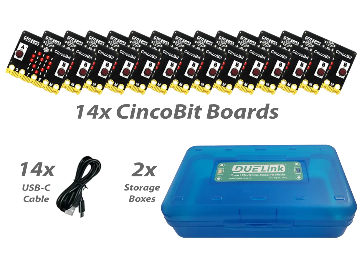
Don't have a board yet? The Classroom CincoBit Kit is the fastest classroom start. For a single board, CincoBit or PixoBit covers most lessons.
Classroom curriculum
Teaching with CincoBit or PixoBit? DUELink includes a complete middle-school CS curriculum — lesson plans and MicroBlocks projects, ready to run in the classroom.
See also For Educators for classroom kits and the typical teaching path.
Two ways to use it
1. Run MicroBlocks on the board — load MicroBlocks firmware on a DUELink board like CincoBit or PixoBit. Your blocks run directly on the module. Follow the CincoBit curriculum for structured classroom lessons.
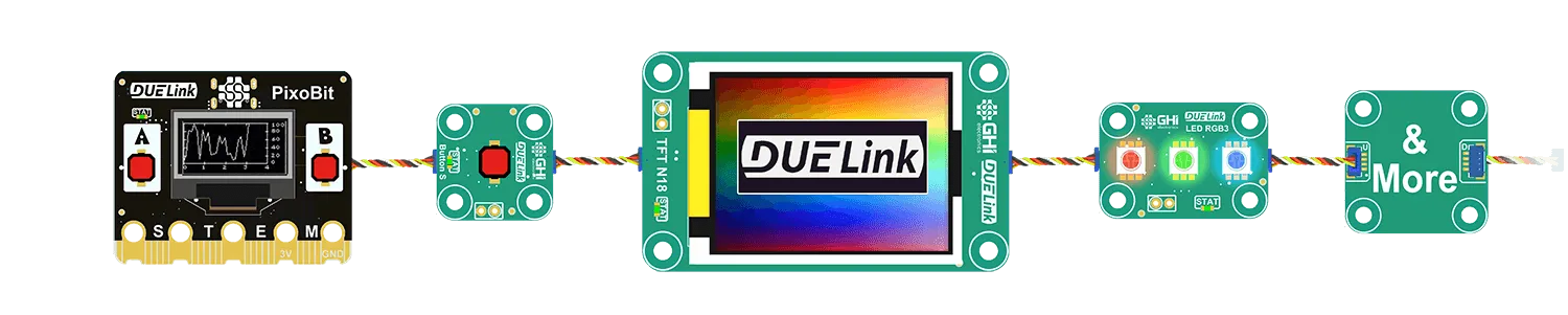
2. Control other modules from MicroBlocks — MicroBlocks runs on a host board (a micro:bit, a CincoBit, etc.) and sends plain-text commands to chained DUELink modules — a light sensor, RGB LEDs, a display, and more. See Chain modules.
You can combine both: MicroBlocks on a board like CincoBit, with more modules chained on the Downlink port.
Product pages list example projects under Commands → Samples (host-side) and On-Module Code (runs on the board).
Get started on the board
Educational boards like CincoBit and PixoBit ship with MicroBlocks pre-loaded. For other modules, use loader.duelink.com/microblocks.
You only need to install or update MicroBlocks firmware when switching from DUELink firmware, or when updating to a newer version.
Open the editor
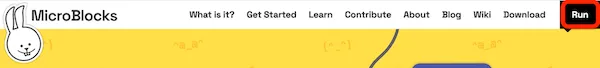
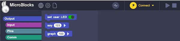
Run MicroBlocks in Chrome or Edge at microblocks.fun — click Run in the top menu, or go directly to microblocks.fun/run.
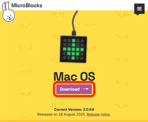
Or download the desktop app for Windows, macOS, or Linux from the MicroBlocks download page.
Connect your board
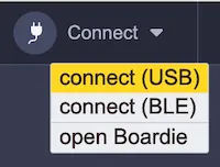
Click Connect in the editor:
Choose Connect (USB):
Select DUELink MicroBlocks, then click Connect:
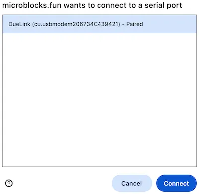
If the board does not appear, check the USB cable and press the board's reset button.
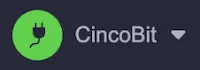
When connected, the button turns green and the board name appears beside it:
First project
Click the file icon and choose New:

MicroBlocks loads libraries for your board:
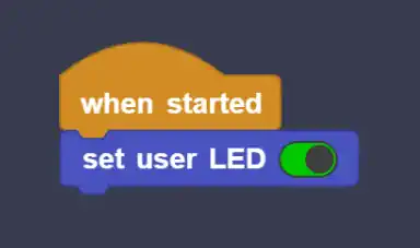
Click the set user LED block in the Output category to verify everything works:

On most boards this turns on the green STAT LED. On CincoBit (no STAT LED), it lights the center pixel on the 5×5 matrix.
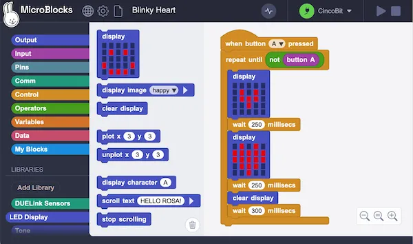
Live coding
MicroBlocks is live — click any block or script to run it immediately:
Drag blocks into the scripting area to build programs. Code is saved in flash and keeps running when you unplug USB.
Scripts that start with when started run automatically on power-up:
Up to ten scripts can run at the same time.
Example projects
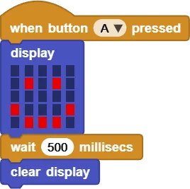
CincoBit — button toggles smile / frown on the LED matrix:
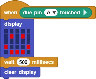
Clipit — same idea using the A touch pad:
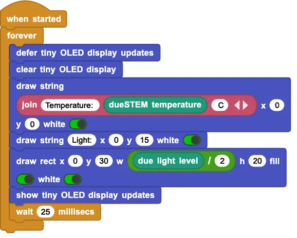
DueSTEM — light level as a bar graph, temperature on screen:
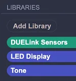
Click Add Library in the editor for nearly 200 extension libraries beyond the defaults.
Pin numbers
On CincoBit and PixoBit, MicroBlocks uses the same edge-connector pin numbers as the micro:bit. Pins 0, 1, and 2 are the alligator-clip holes on the left side.
On CincoBit: pin 9 = light sensor, pin 21 = buzzer.
On PixoBit: pin 21 = buzzer, pin 22 = display reset, pin 23 = light sensor.
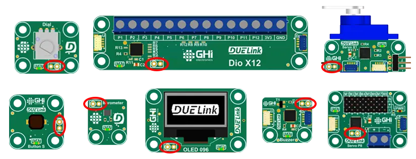
On all other DUELink boards, MicroBlocks uses standard DUELink pin numbers. Pins 0–9 and 17 support analog input. Pin numbers are marked on the board or in its schematic.
Control chained modules
MicroBlocks on one board can command other DUELink modules over the chain. The host runs MicroBlocks; downstream modules keep DUELink firmware and respond to text commands — the same commands listed on each module's Commands tab.
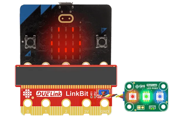
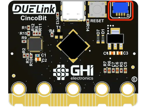
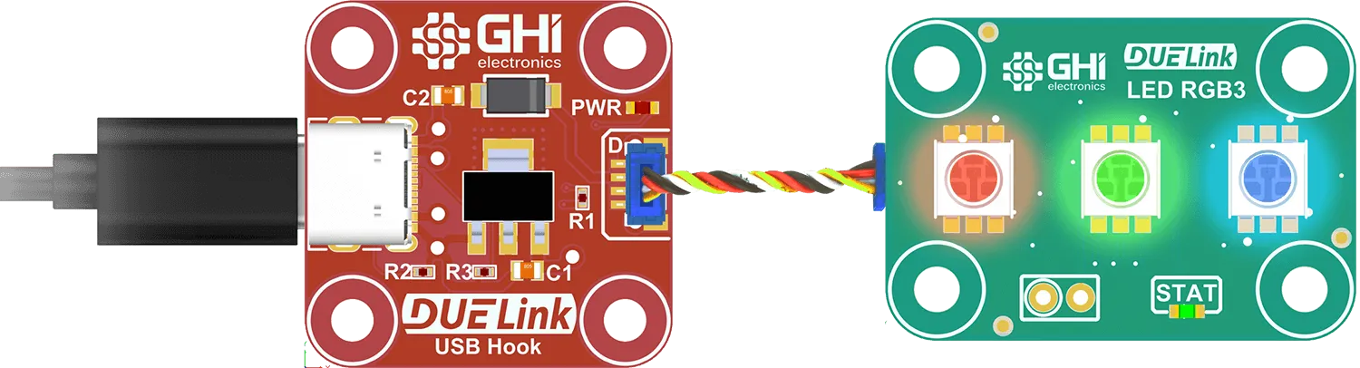
micro:bit → LED RGB3 — MicroBlocks on the micro:bit, LinkBit adapter for the JST Downlink port:
PixoBit → chained modules — MicroBlocks on PixoBit controlling a Downlink chain:
Wiring
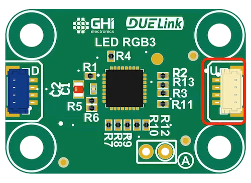
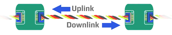
Connect the host board's Downlink (D) port to the first module's Uplink (U) port:
Chain additional modules: each module's D connects to the next module's U.
Modules can mount on a Holey Board.
For a non-DUELink host (e.g. micro:bit), use LinkBit or wire I2C/UART through a Breakout. Full details: Chain modules.
Always connect D → U. A D–D or U–U link anywhere in the chain will not work.
Disconnect USB/power before plugging or unplugging modules. DUELink assigns addresses on power-up, so power-cycle after wiring changes.
Add the Daisylink library
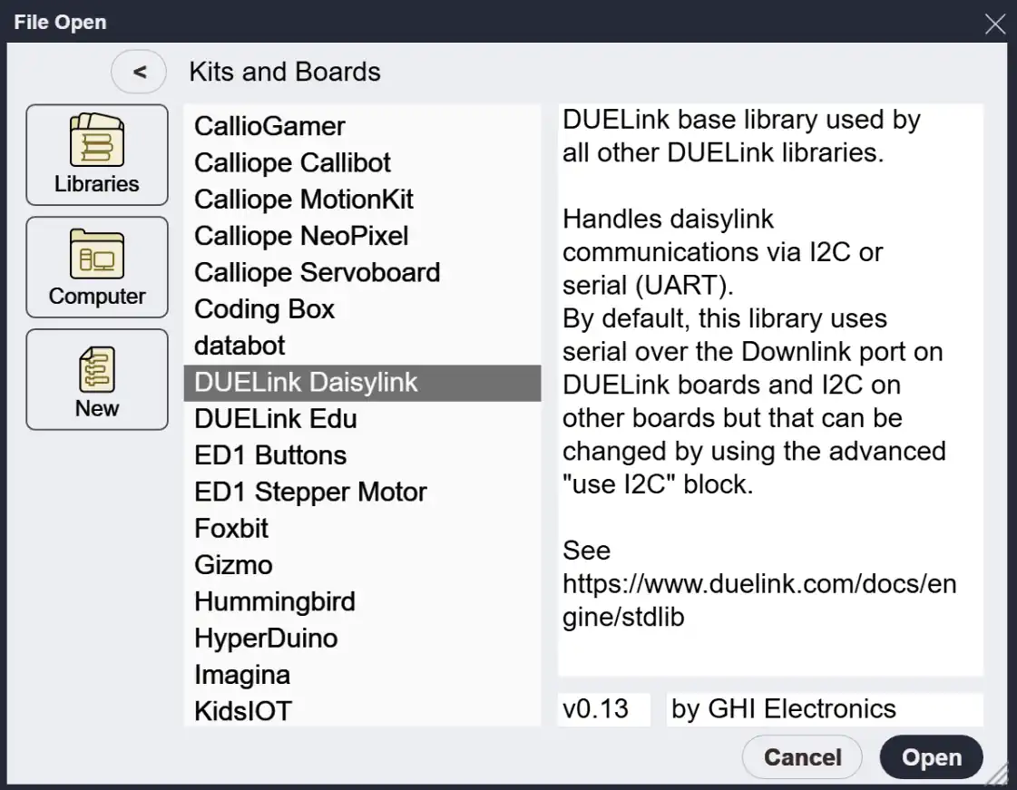
In the MicroBlocks editor, click Add Library → Kits and Boards → DUELink Daisylink:

Click the connected? block to confirm the downstream module is detected:
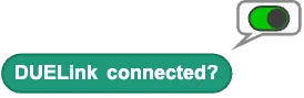
Modules cannot be hot-plugged. If connected? fails, check wiring and power-cycle the whole chain.
The first module in the chain is address 1 (selected automatically on power-up). Use select device when you need address 2, 3, and so on.
Using module commands
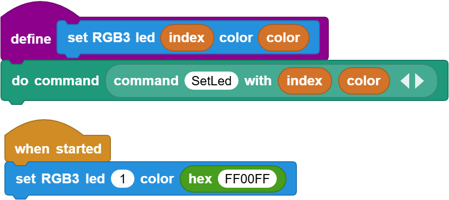
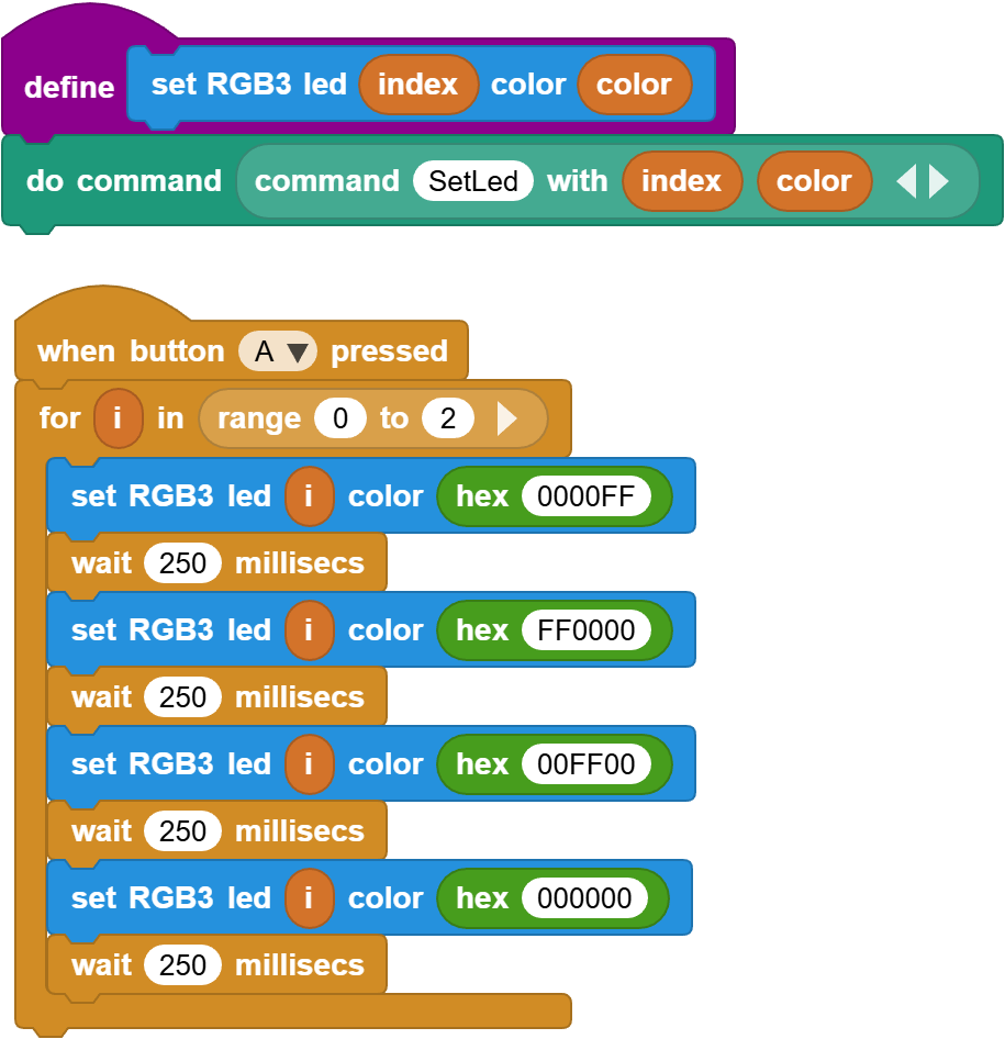
Each chained module exposes commands through its driver — see the Commands tab on its product page. For LED RGB3, SetLed(i, c) sets LED index i (0–2) to color c (hex RRGGBB, e.g. FF0000 for red).
The DUELink Daisylink library includes blocks to call these commands. Example helper for RGB3:
Check Commands → Samples → MicroBlocks on a product page for a ready-made project you can open in MicroBlocks.
Press button A to cycle RGB3 through red, green, and blue:
Going further
MicroBlocks on any module
You can load MicroBlocks firmware onto any DUELink module, not just classroom boards. LED RGB3 is a common example — use a USB Hook since it has no USB port:
Put the module in DFU mode via the Loader Erase All flow, or short the BOOT0 pads while powering up:
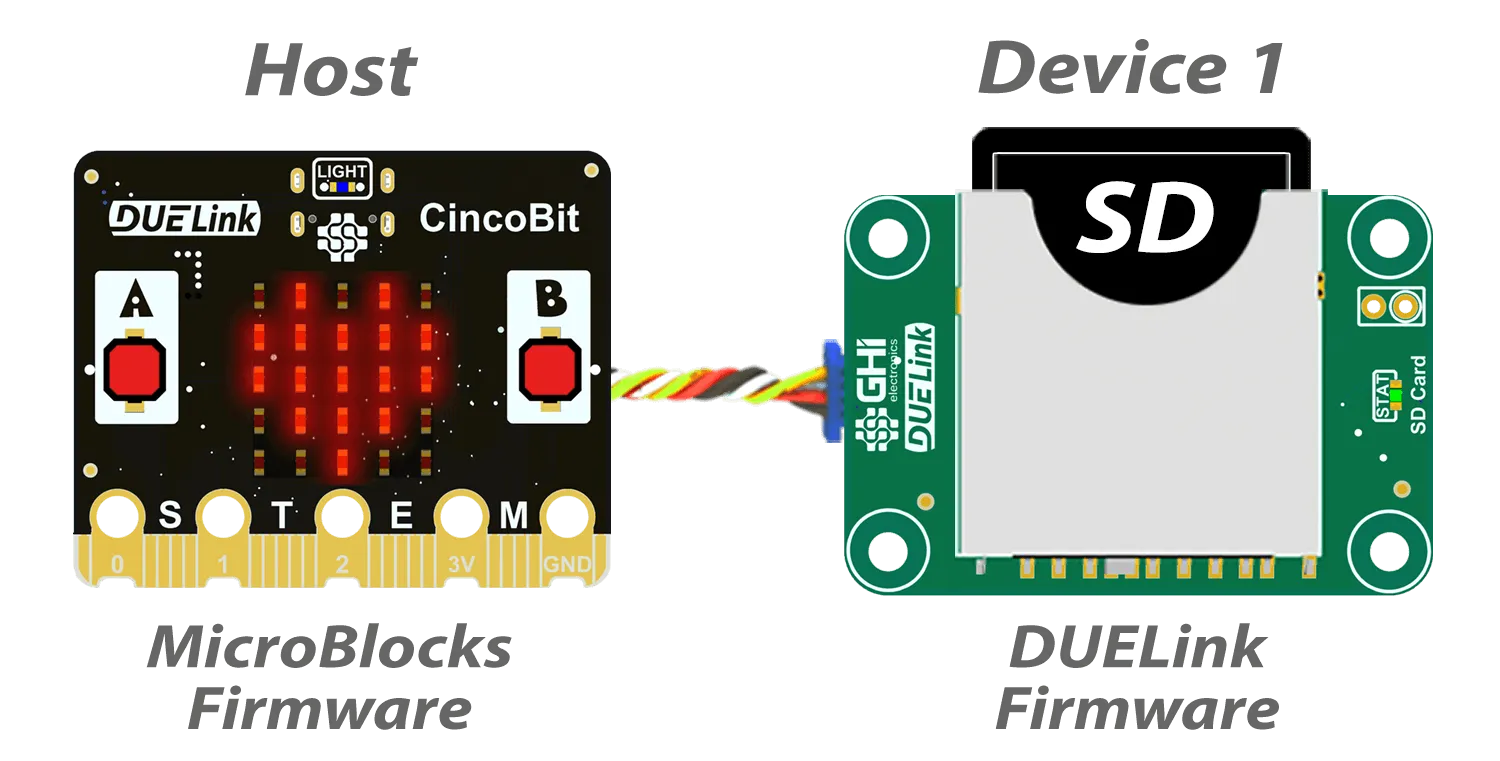
Once MicroBlocks firmware is loaded, the module no longer accepts DUELink text commands — you control hardware entirely through MicroBlocks blocks. Simple modules (LEDs, buttons, sensors) are straightforward; complex ones (displays, SD card, USB host) are easier to chain so the module keeps its DUELink firmware and built-in command support.
Example: run MicroBlocks on CincoBit and chain an SD Card module instead of loading MicroBlocks on the SD module itself:
Linux
Linux may need dialout group membership for USB serial access. See the Linux tab on MicroBlocks Get Started.
Example Linux setup script
#!/bin/bash

echo "Adding user to dialout group for serial port access..."
sudo usermod -aG dialout $USER

if id -nG "$USER" | grep -qw "dialout"; then
    echo "User $USER added to dialout group successfully."
else
    echo "Failed to add user to dialout group."
    exit 1
fi

echo "Creating udev rule for STM32 DFU mode..."
echo 'SUBSYSTEM=="usb", ATTR{idVendor}=="0483", ATTR{idProduct}=="df11", MODE="0666"' | sudo tee /etc/udev/rules.d/99-stm32-dfu.rules > /dev/null
sudo udevadm control --reload-rules

echo "Log out and back in (or reboot) for changes to take effect."
Save as a .sh file, chmod +x, run once, then reboot.