Daisylink
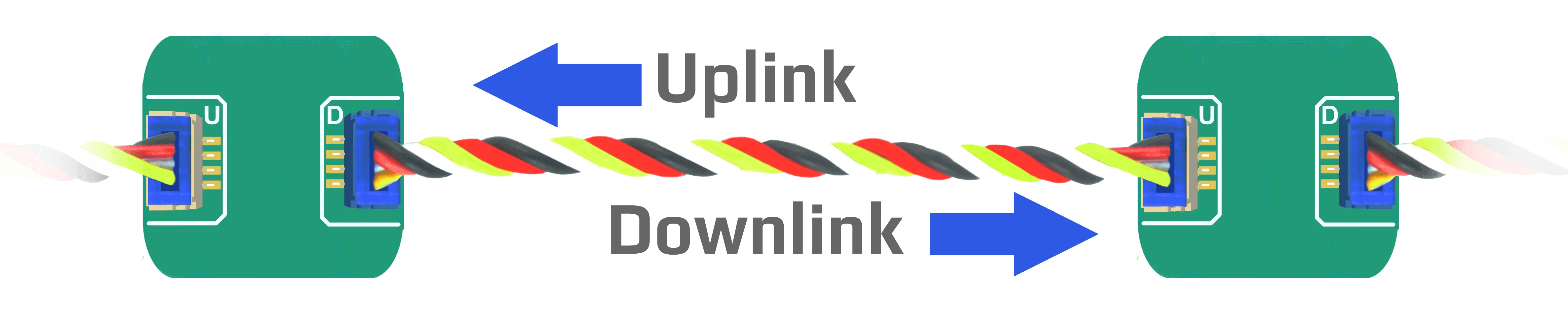
DUELink allows multiple modules to be chained together, creating a Daisylink. Commands flow into a module via its Uplink connector (White) a then forward the command out on its Downlink connector (blue). Each module in a Daisylink is a signal repeater. There will be no degradation of the signal quality.
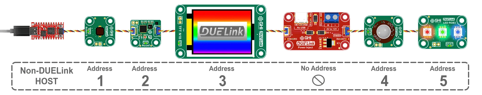
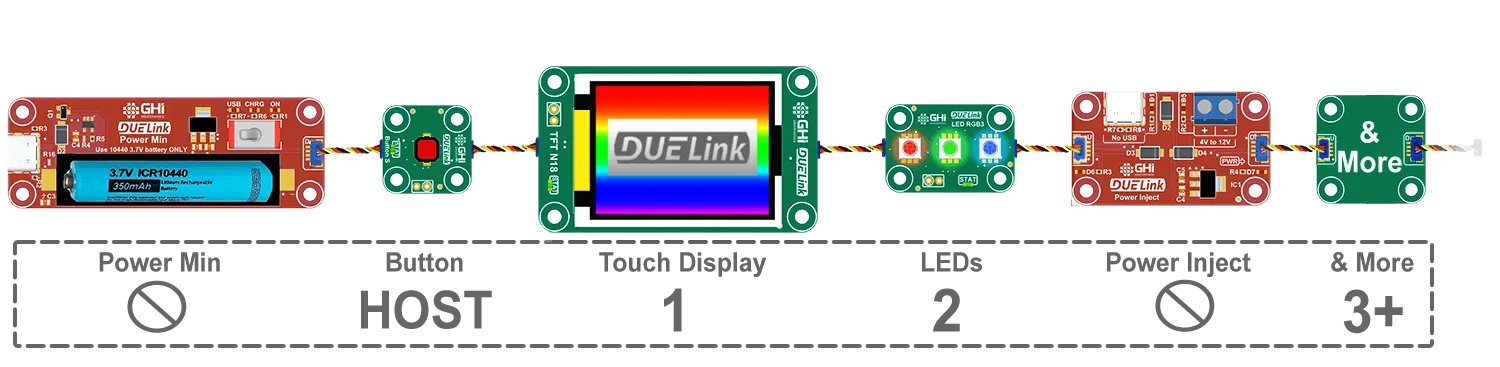
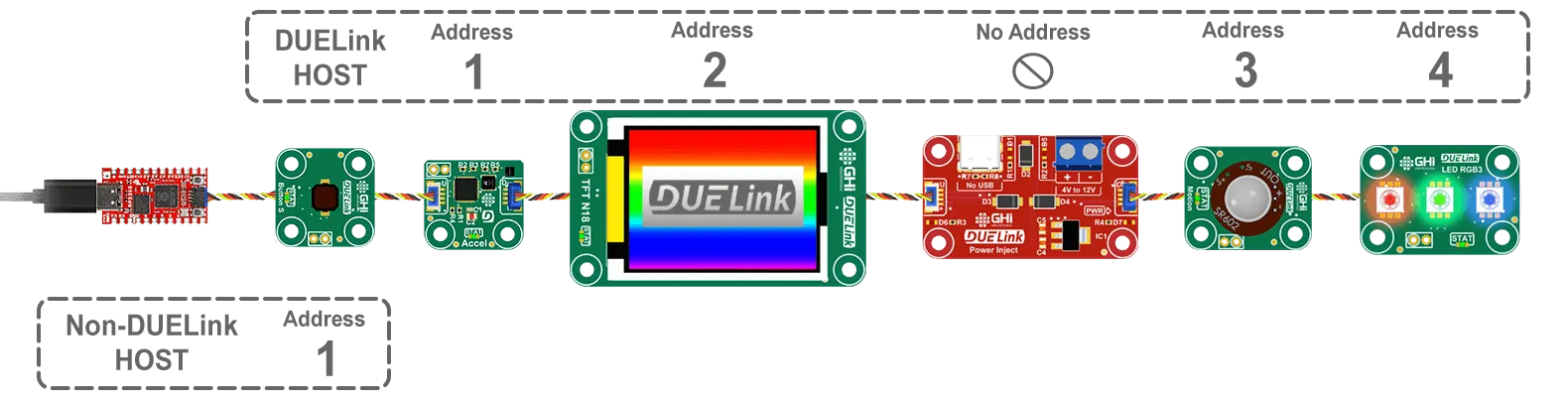
If necessary, add Power Inject adaptor to help in powering devices on its Downlink. Adaptors usually have no intelligence and therefore do not carry an address. They are usually red circuits. In this example, a host (PC/Arduino...etc.) is controlling a Daisylink of modules, starting with a button at address 1. Power inject will not have an address and the following module will be address 4.
Device Selection
The Standard Library offers the Sel() command to activate devices on the chain. To blink the status LED on the second device on the Daisylink chain, the host will issue Sel(2) followed by StatLed(200,200,50). The LED will blink 50 times on the second module in the stream.
The Sel() command is not like other functions found in the standard library as modules can't self select. Only the host can issue Sel().
In other words, do not add Sel() inside a script.
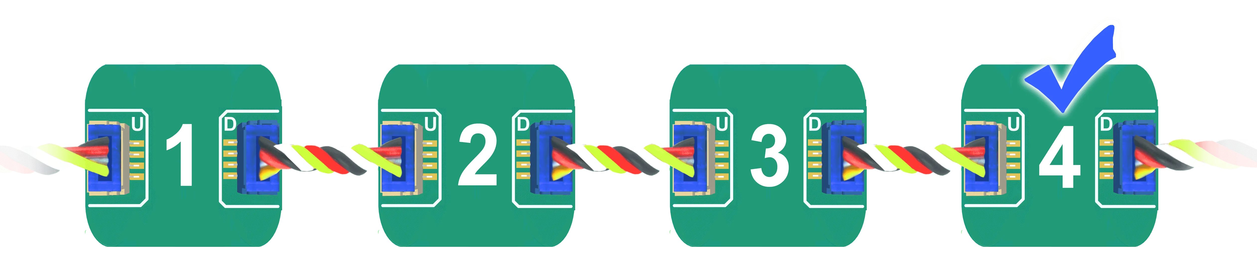
Daisylinked devices on a stream are addressed by their count, starting with 1 as the first module connected to a host. The fourth device on the bus is selected using 'Sel(4)'.
Any module can turn into a "Host", which is covered later on this page.
Broadcast
Address zero is a special address on the chain, which indicates a broadcast selection. During a broadcast, all modules are required to process the command.
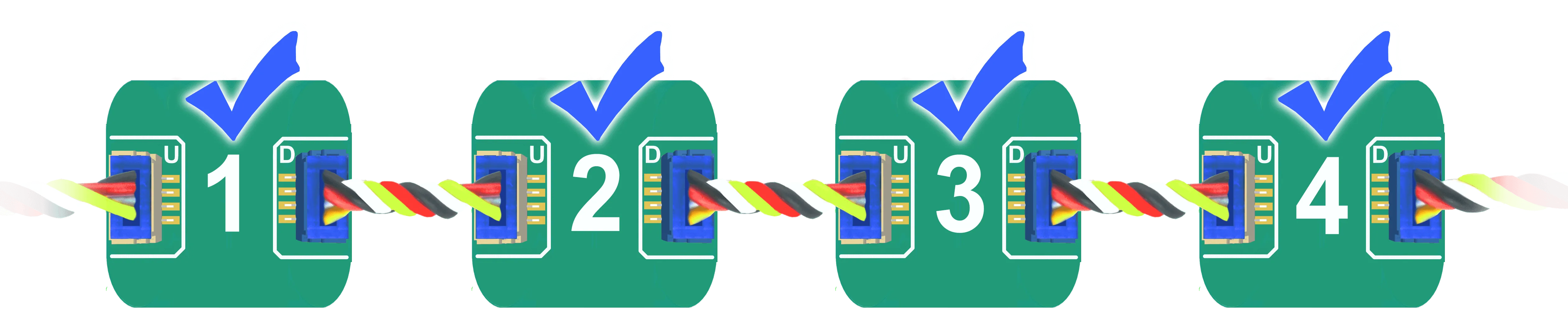
In this example, we have 4 modules connected.
Sending Sel(0) followed by StatLed(200,200,50) will blink the status LED 50 times on each one of the four modules.
While it is also possible to read from multiple devices, Sel(0):Print("Hi"), this is not recommended as responses come back as out-of-order.
It is also possible to select more than one device at once, multi-select. Here is how to select devices 1, 3 and 4 Sel(1,3,4).

Same as for Sel(0), reading responses in a multi-select setup is not supported.
Device Enumeration
When modules power up, they have a NULL interface, and they have no set address yet. Once an Interface is detected, such as USB, then the first device will set its own address to 1 and then command all Downlink devices to take a new address. This causes a chain reaction , 1, 2, 3, 4...etc.
To initiate the Daisylink and enumerate the modules connected on the Downlink interface, a command must be sent. This very first command is only seen by the first device. An empty command (just a carriage return) can also be used, and is recommended.
Only smart modules receive an address. For example, both power modules in this Daisylink do not have an address.
Use GetAddr() to read the current selected device address. If the current address is zero, then the module has not been enumerated yet. GetCnt() can be used to return the count of connected modules, as seen by the host. Note that when there is a module in the chain that is configured as "Host Mode" then the main host will only see the modules up to that module in "Host Mode".
Since devices get enumerated in a sequence plus each module needs about 2ms to be ready, commands should not be sent to modules for 2ms for each module in the Daisylink. For example, wait for 10ms before commanding a Daisylink with 5 modules.
Host Mode
In most cases, DUELink modules connect to third-party Supported Hardware device. This device is the Daisylink host.

Addressing is simple normal use, starting with address 1. Adaptors, like Power Inject, do not have an address.
DUELink modules can also run Standalone and be in "Host Mode", hosting one or more Daisylinked modules, connected to its Downlink socket.
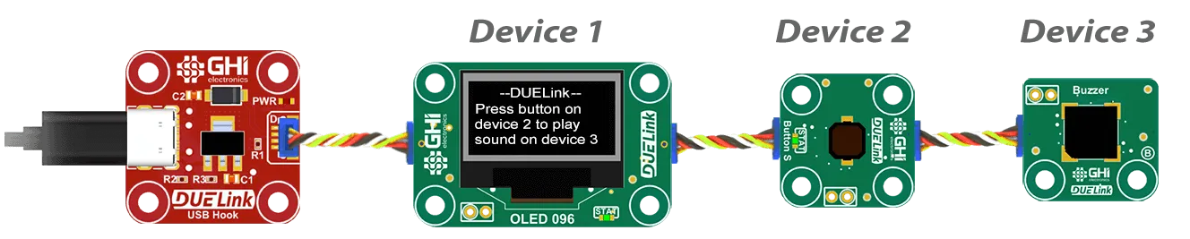
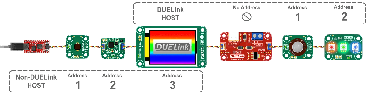
The host-mode-module can be anywhere in the chain. Here is an example where the third module is configured in "Host Mode". Note how the host module is address 3 to its host, which is the Sparkfun micro in this example. The other modules on its Downlink also have addresses starting at 1, but these are only visible to their host, which is the display.
This host can also be anywhere else in the link, including the first device. Think of modules as always physically connected but logically separated and controlled by their own respective host.
As documented on the Downlink interface page, DLMode(2,0) command is used to switch the module to host mode. This will automatically reset and re-enumerate thats host's clients.
Internally, the module that is becoming a host will send SetAdd(0) for all its modules to release their addresses and close their downlink ports. It then send a "new line" to start the automatic enumeration process.
For demonstration, use the Console to load this code on the second module. This code will enable "Host Mode", which will break the chain at the second module. The code then sends a commands to its clients. It is important to note how the code sends Sel(2) using Cmd(). A Module can not self select or call Sel() in its script. Use Cmd(Sel(2)) to select the second module.
Loading scripts from a PC can be done on modules connected onto the main link only, up to the in-line host. Remember, adding a host in the middle of a chain logically breaks it into multiple chains.
DLMode(2,0) # Switch Downlink to host mode
Wait(100) # This delay is more than enough for 50x modules.
Cmd("Sel(2)") # Select second device
Cmd("StatLed(200,200,50)") # Blink the LED 50 times on the selected device
This is what the link would look like.
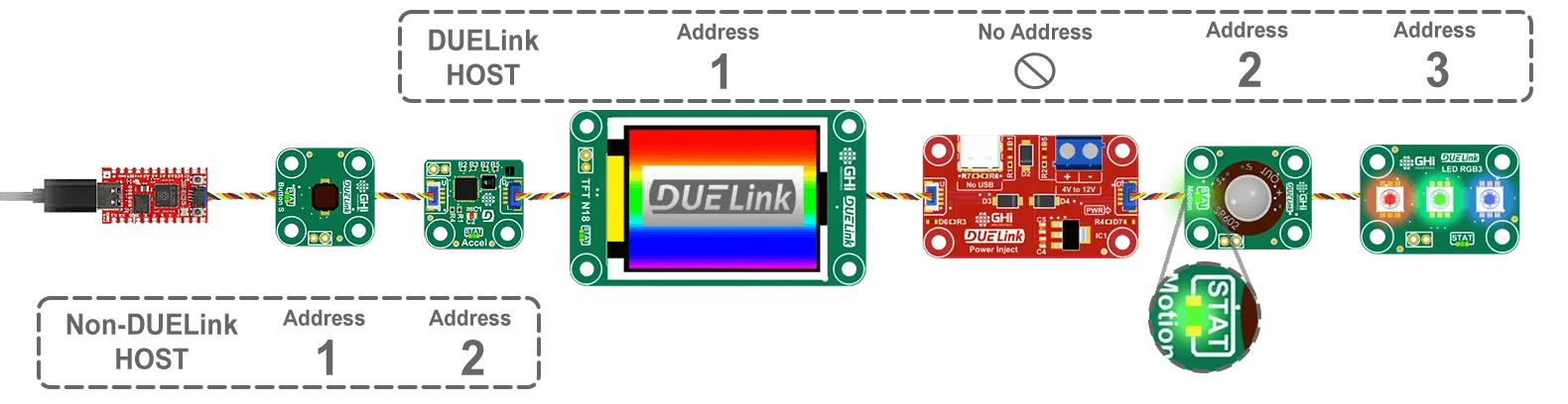
Note how there are 2 modules with address 2, each one visible only to its host.
A module in "host" mode is still listening to commands coming from Uplink, from its host, but it does not forward the commands Downlink. This allows for programming and configuring the host, from DUELink Console for example.
Considerations when using host mode:
- While possible, do not use more than one host in a Daisylink.
- While possible, use host mode on the first module in the chain.
Cloning
One updated module can copy its firmware to the next module in the chain. See Cloning for details and scripting examples.
Wireless
It is also possible to use a wireless connection to Daisylink!
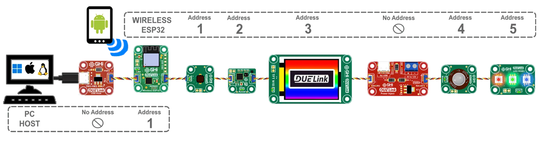
See Wireless interface page for more info.