Interfaces
A DUELink module receives simple text commands over a physical bus — USB, I2C, or UART — and sends responses back the same way. The bus is the interface.
For example, sending StatLed(200,200,5) over the interface blinks the on-board STAT LED five times. Every module understands a common set of commands like this, plus its own module-specific ones — see Get Started for the full picture and each product's Commands tab for what it supports.
Any host that can write text can drive a module: a PC, Raspberry Pi, Arduino, micro:bit, phone, or another DUELink microcomputer.
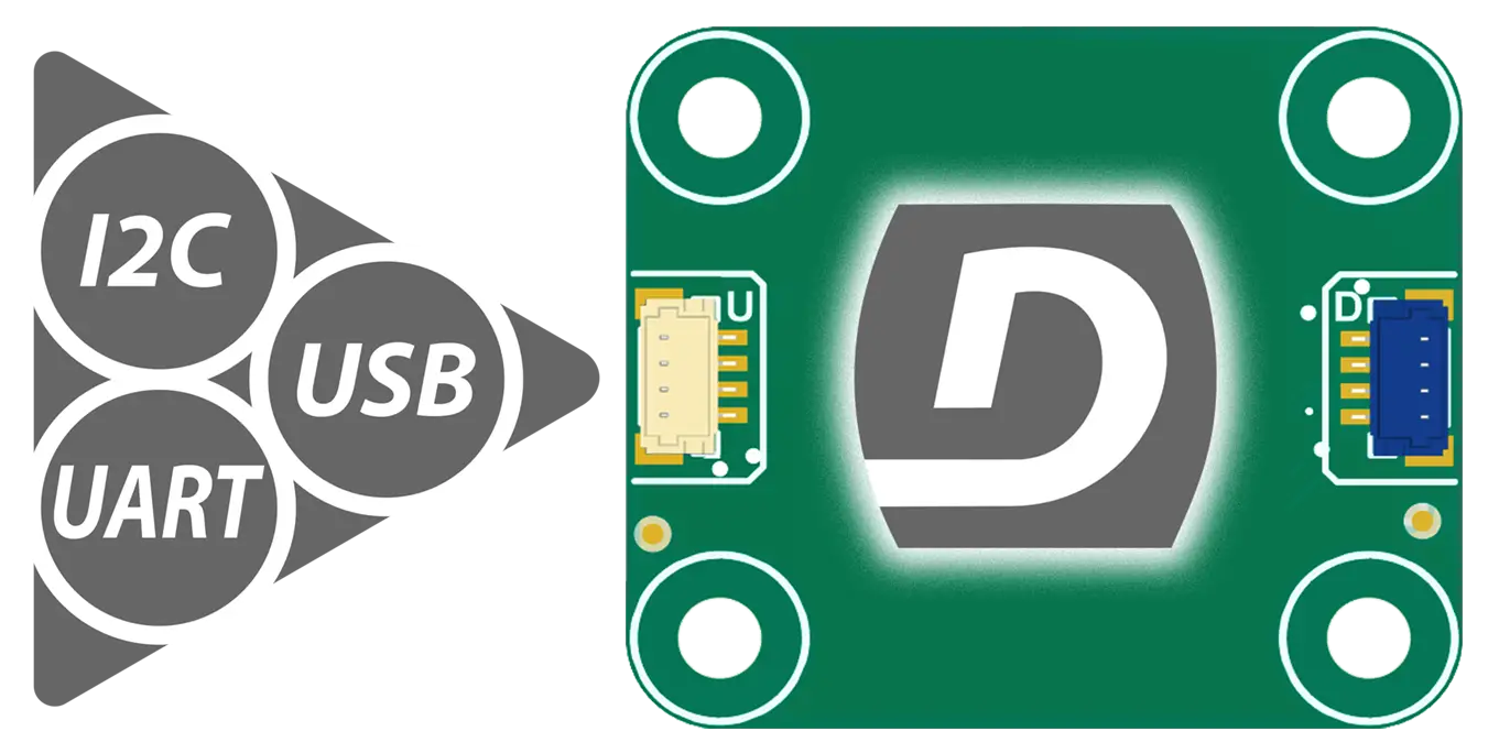
Every module has two JST connectors — Uplink (white, marked U) and Downlink (blue, marked D) — that work together to let many modules be chained into a Daisylink.
Uplink: where commands come in
The Uplink connector is the module's input port. It accepts commands from either a host or the previous module in a chain.
Uplink supports all three buses — USB, I2C, and UART — through the same physical connector. The module detects which one is active on power-up (see Interface Detection below).
Microcomputer variants
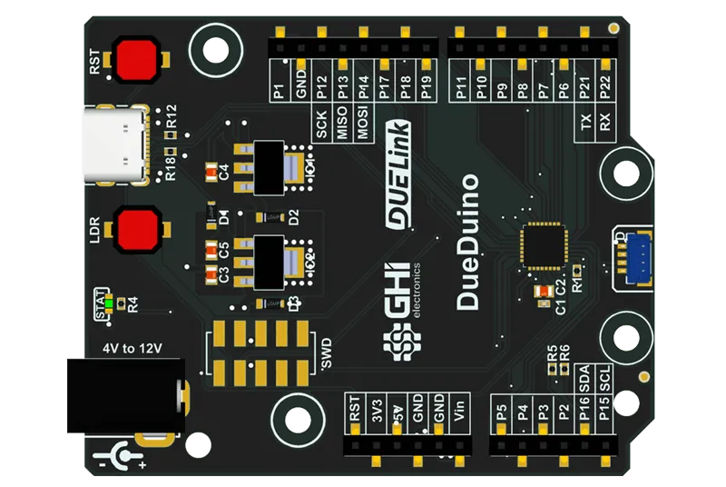
Some modules — the microcomputer form factor — replace the JST Uplink with a direct USB connector. These can only use the USB interface.
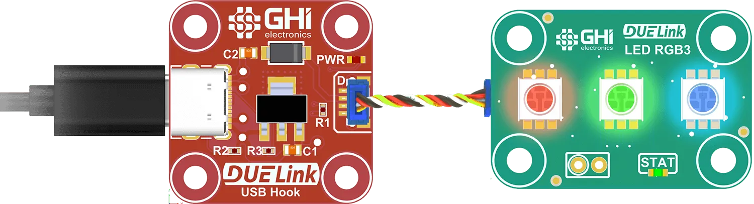
Modules with only a JST Uplink can still connect to a PC through a small adapter like USB Hook.
Downlink: where the chain continues
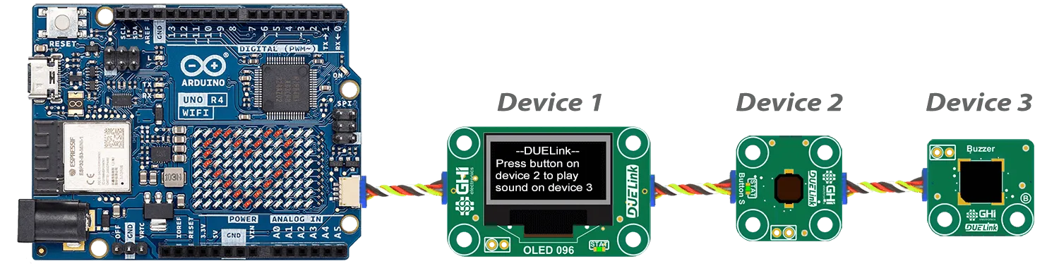
The Downlink connector is the module's output port for adding more modules. Plug the Uplink of the next module into the Downlink of the current one, and commands flow through.
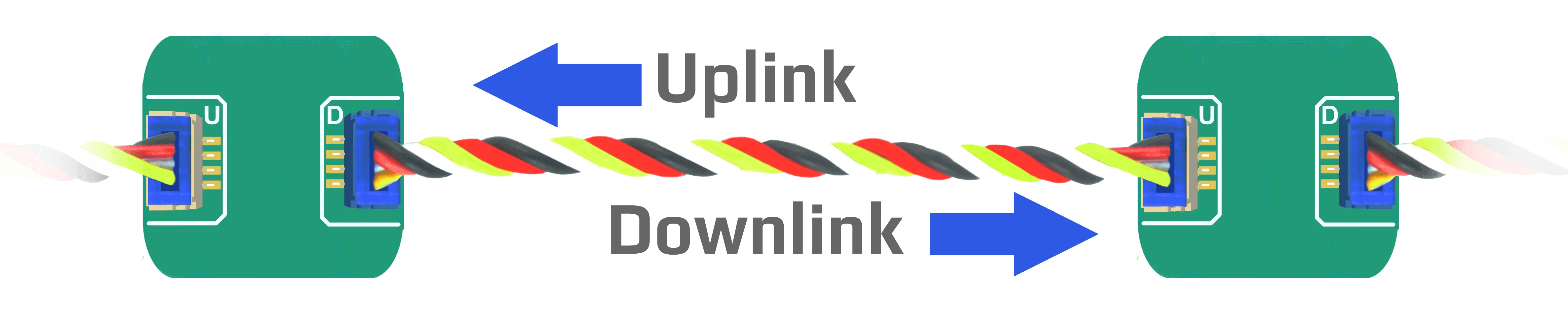
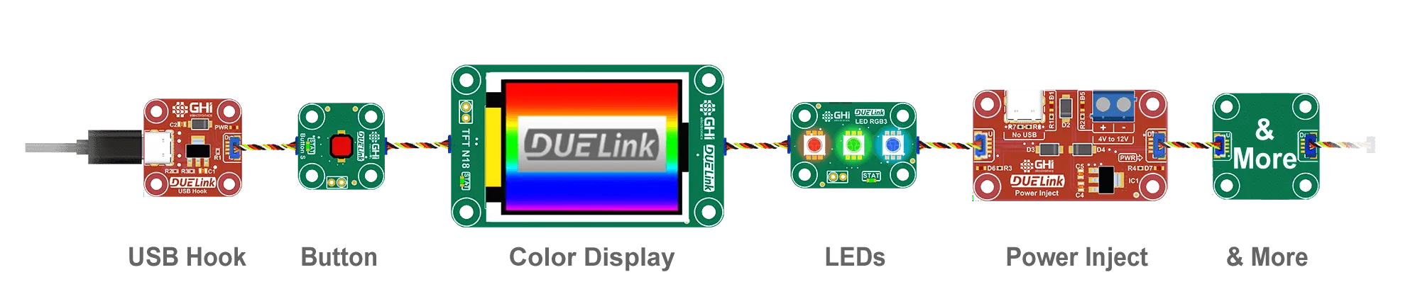
The pattern is: host → Uplink of module 1 → Downlink of module 1 → Uplink of module 2 → Downlink of module 2 → ... Each module is a signal repeater along the way, and each one gets its own address (1, 2, 3, ...) assigned automatically on power-up. The host selects which module a command targets with Sel(n).
Downlink is handled automatically by the internal engine. For the full picture — addresses, broadcast, multi-select, and host mode — see Daisylink.
Wireless
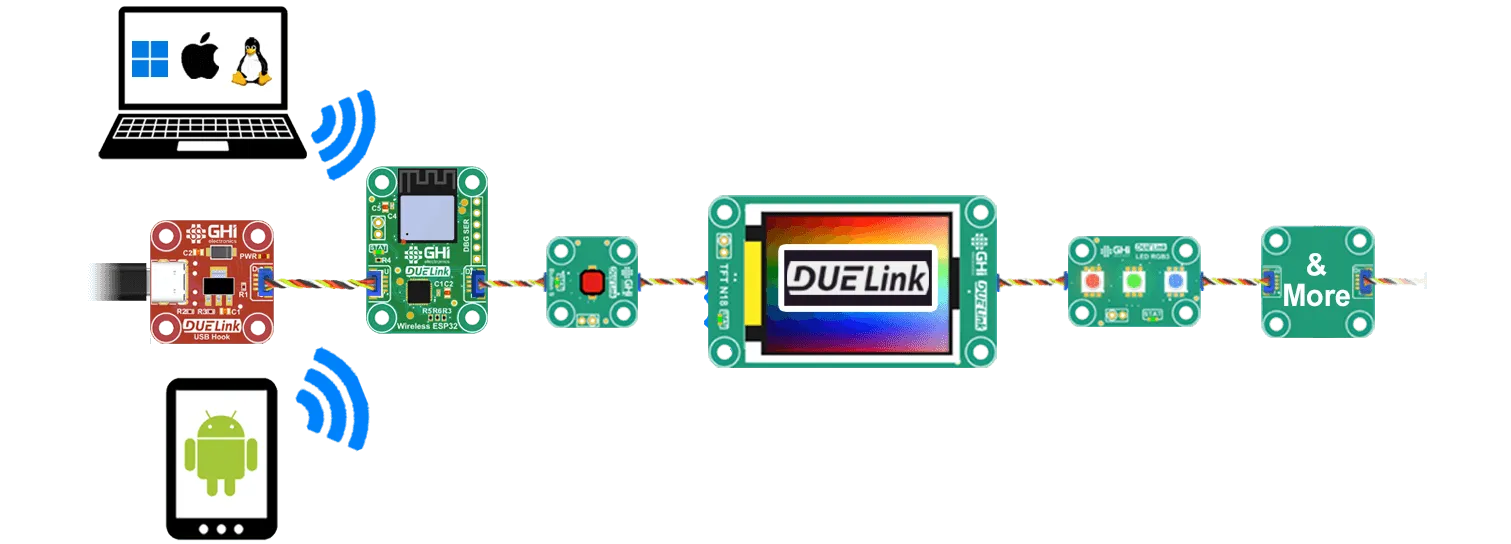
The chain doesn't have to be physical — a wireless link can carry commands between segments of the same Daisylink.
Interface Detection
On power-up, a module checks its interface pins. If both are pulled high, it configures itself for I2C. Otherwise it watches for activity on USB or UART and selects whichever wakes first.
Connector safety
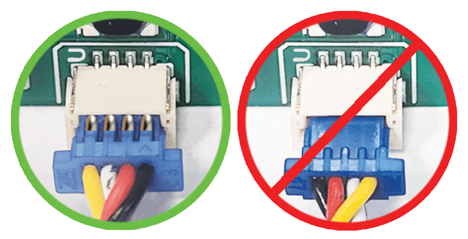
See Connector Safety for how to handle JST connectors without damaging them.