I2C
I2C is the most common interface when selecting a microcontroller-level Hardware.
Host Boards
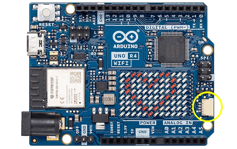
Many host boards today include JST connectors that use I2C bus. A good example is Arduino UNO R4 WiFi. Arduino is one the Supported Hardware options, providing all the necessary libraries.
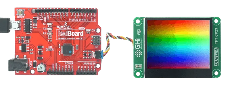
Another example is Sparkfun Redboard.
The Protocol
A DUELink module is always an I2C slave listening to an I2C bus master on address is 0x52 (7bit), which is fixed and can't be changed.
The host (I2C master) can send data as individual bytes or multiple bytes. The module will look at individual bytes and disregard how they're packed in I2C frames. In other words, start, restart, and stop conditions are ignored by the data stream.
The module (I2C slave) will return 0xFF when the host requests data with no available data to return. This is works well in most cases as 0xFF is not used in commands and responses as they are all readable ASCII. However, in cases when the slave needs to send 0xFF as an actual data, it will instead send 0xFE followed by 1. And similarly, to send 0xFE it will instead send 0xFE followed by 2.
This code explains how to process received I2C data.
escape = false;
error = false;
ProcRxI2C(b)
{
    if(escape)
    {
        if(b == 1)
            InsetFifo(0xff);
        else if(b == 2)
            InsertFifo(0xfe);
        else
            error = true;
        escape = false;
    }else
    {
        if(b == 0xfe)
            escape = true;
        else if(b == 0xff)
            return;
        else
            InsertFifo(b);
    }
}
When the device is too busy to accept data, it will use clock stretching feature. Clock stretching support is a standard I2C feature and is required from the host.
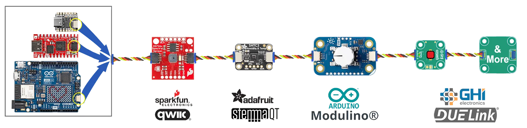
Non-DUELink Modules
Many modules on the market include a JST connector with I2C bus signals. They simply use I2C and most will not have any intelligence. DUELink gracefully allows for these modules to be connected on the same Daisylink. The only rule is you have to connect the non-DUELink modules first in the chain. Access those module like you normally would, as DUELink will simply ignore them.
You can't use any non-DUELink modules that have the same address as DUELink, which is very unlikely!
Non-DUELink use I2C, where each module has its own slave address, such as the case with Sparkfun QWIIC and Adafruit STEMMA modules. There will also be signal degradation when having long wires or many modules.
While the connector and the chain look similar, DUELink works differently. I2C is only used at the first module connection. Then that module connects to other modules using the Downlink interface. This typology does not consume I2C addresses and allows for Daisylinking hundreds of modules!
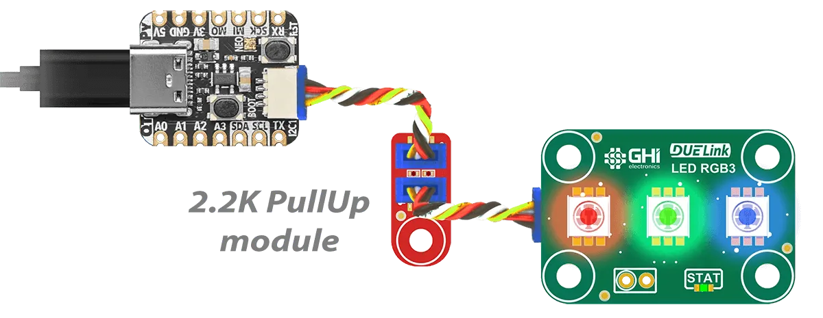
Pull Up Resistors
I2C requires pull up resistors to operate, typically 2.2K. Some boards on the market do not include these resistors. Instead, they rely on the internal weak pull up resistors inside the micro. This may cause problems in some cases. DUELink has a PullUp module to solve this issue.