Downlink

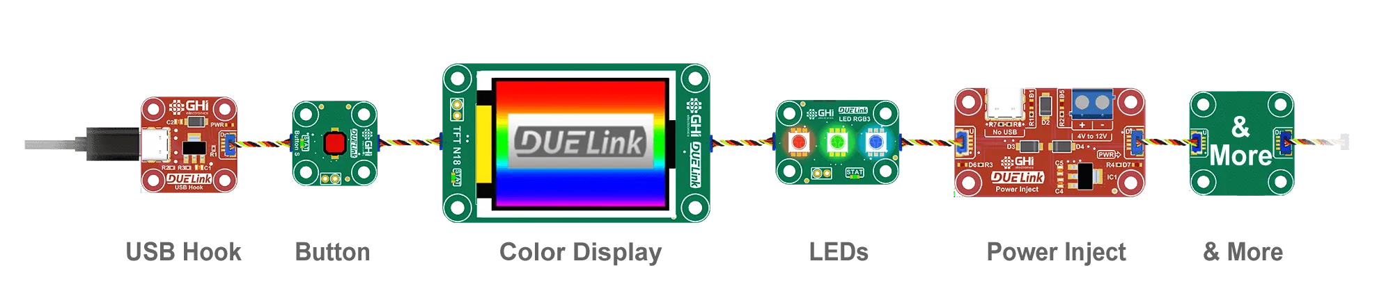
The Downlink connector found on every single DUELink module is used to connect to the next Uplink connector on the next module. The DUELink software magically handles the data going across the entire Daisylink chain of connected modules.
Signal Integrity
There will be no signal degradation along the wires as data is repeated on every Downlink connector. In cases where power is dropping after several modules, a Power Inject module can be used.
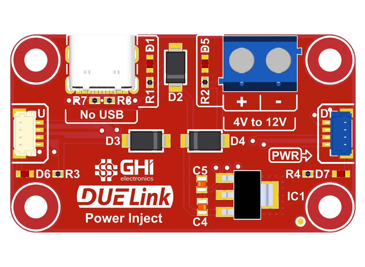
This is not necessary in most cases since modules are very low power. However, large displays and motor drivers may require a decent amount of power.
Modes
The Downlink connector has multiple modes, to give the user more control. See DLMode(mode, config) in Standard Library.
| Mode | Config | Description |
|---|---|---|
| 0 | None | Null |
| 1 | None | Daisylink |
| 2 | None | Host |
| 3 | {Pin, level} | Passthrough (deprecated) |
| 4 | None | Inactive |
| 5 | None | I2C |
On power up, the Downlink connection is Null. To initiate the Daisylink and enumerate all connected modules, a command must be seen by the first module, even if it is a single module. This very first command is only seen by the first module and discarded by others. We recommend using an empty command (just a carriage return) to initiate the module enumeration and addressing. Upon enumeration, Downlink is switched from Null to Daisylink mode automatically.
The user has the option to switch to Host, Gateway, or Inactive modes at anytime. However, once switched to these modes, the user can only switch between these modes.
Host mode is an option for Daisylink.
Passthrough (deprecated) is used in rare cases where the upstream and downstream UARTs are virtually connected in a passthrough, allowing the system to bridge and pipe the data between upstream and downstream. For config, there is a special pin that will automatically switch downstream mode to Inactive if the pin is at level. The system will not go back to Passthrough mode on its own. It is up to the user to switch to Host or back to Passthrough. For example, DLMode(3, {6,1}) will set the downlink mode to Passthrough and monitor pin 6. If pin 6 becomes high, the system will automatically switch to Inactive. The user may check the current mode using Info(3) to determine the current state.
Inactive disables all communication with downstream.
I2C non-DUELink mode is used to connect other devices, as detailed in the next section. Once this mode is selected, it can't be unselected without a module reset.
I2C Mode
The Downlink connector can be switched to a special I2C non-DUELink mode. This mode will free up the Downlink connector from its normal use, giving the user access to DLI2CWr() function. This will allow for an I2C access on the Downlink connector, see Standard Library.
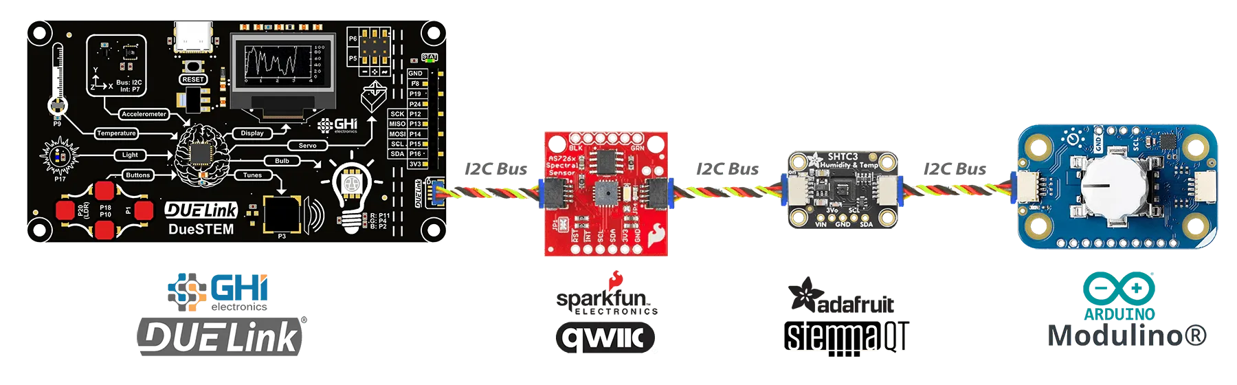
It is also possible to have a Daisylink of DUELink modules where the last module (and only the last module) is switched to I2C non-DUELink mode. This last module can now use DLI2CWr() to access those I2C non-DUELink modules.
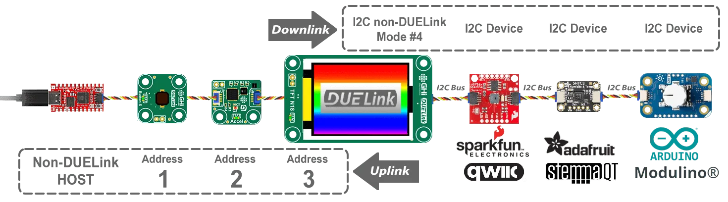
In this mode, I2C bus traffic is simulated over the Downlink connection and the Daisylink bus, causing it to run slower than direct a I2C connection.