Arduino
Use an off-the-shelf Arduino board (Arduino UNO R4, SparkFun RedBoard Qwiic, etc.) as a host that drives one or more DUELink modules. Modules respond to plain-text commands; your Arduino sketch sends them through our library.
Want to load Arduino code onto a DUELink module instead of using a separate Arduino board? See Arduino IDE.
Connect the Arduino to DUELink
Several routes depending on what your Arduino board has:
-
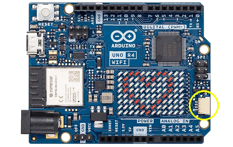
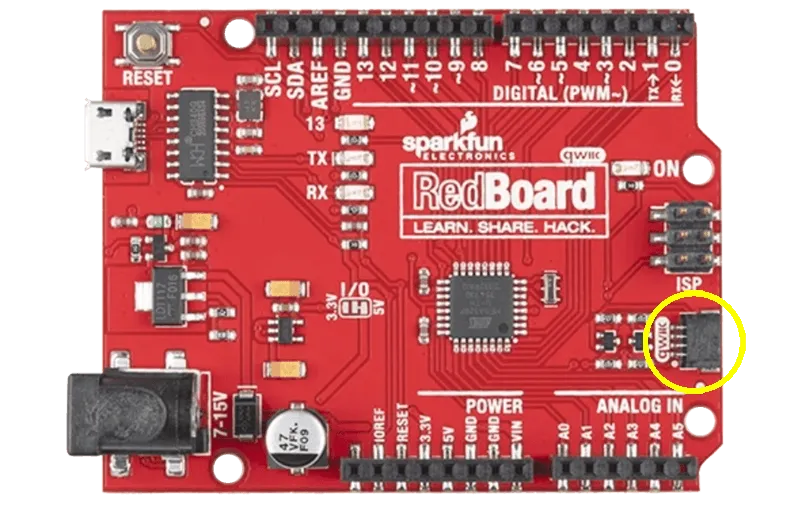
Built-in JST SH connector (Arduino UNO R4 WiFi, SparkFun RedBoard Qwiic, etc.) — plug straight into a DUELink module's Uplink port with a JST cable.
-
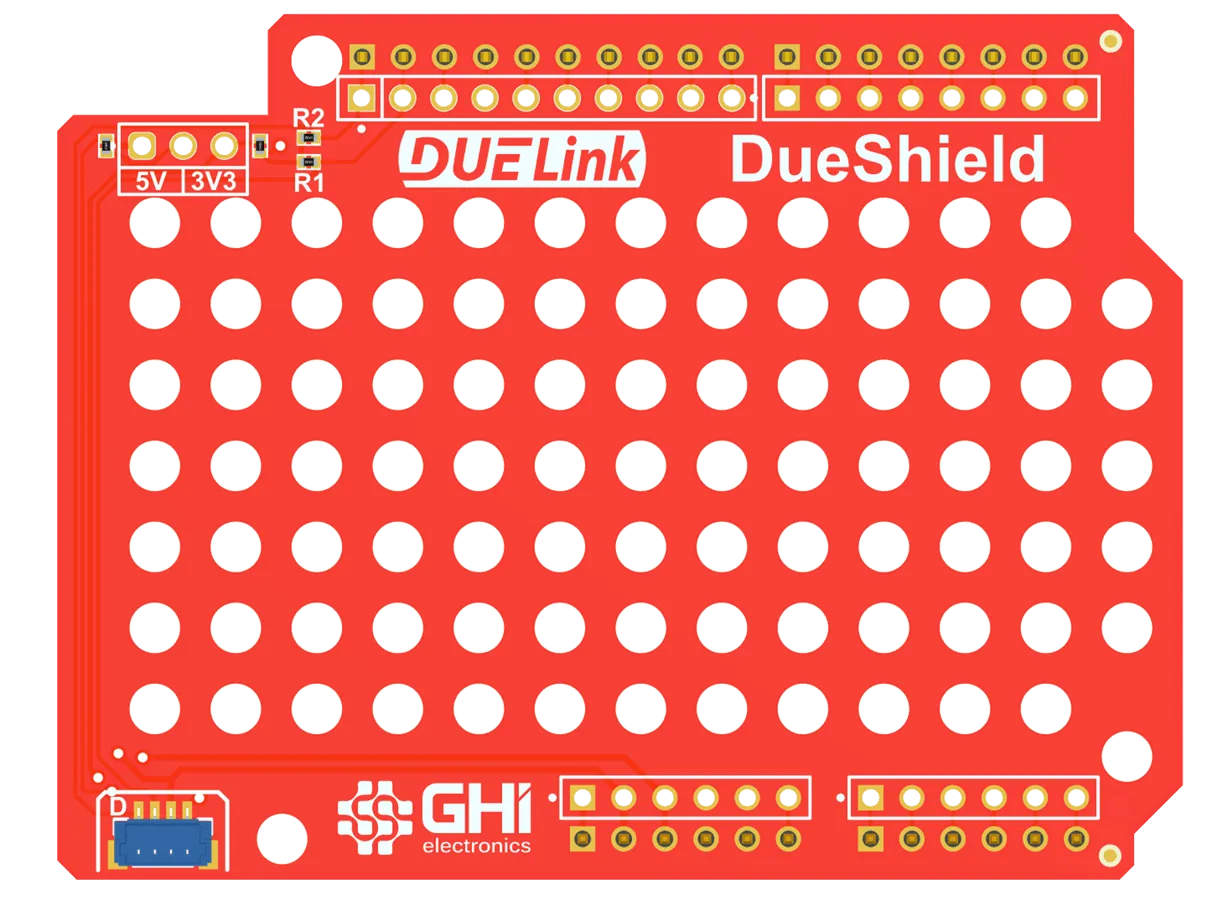
Classic Arduino shield form factor (no JST) — use the DueShield. It exposes a Downlink connector and has a hole-matrix mounting area for DUELink modules.
-
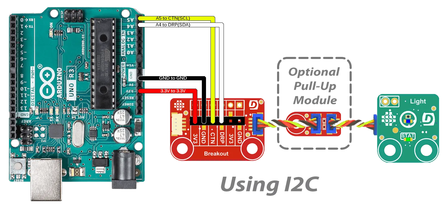
Any board with I2C or UART pins — use the Breakout module to wire to those pins directly.
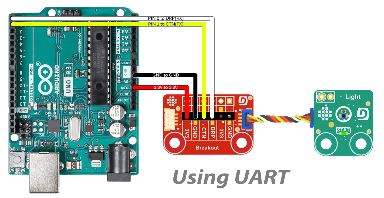
For I2C, your Arduino board needs pull-up resistors. If it doesn't have them, add a PullUp module.
Install the library
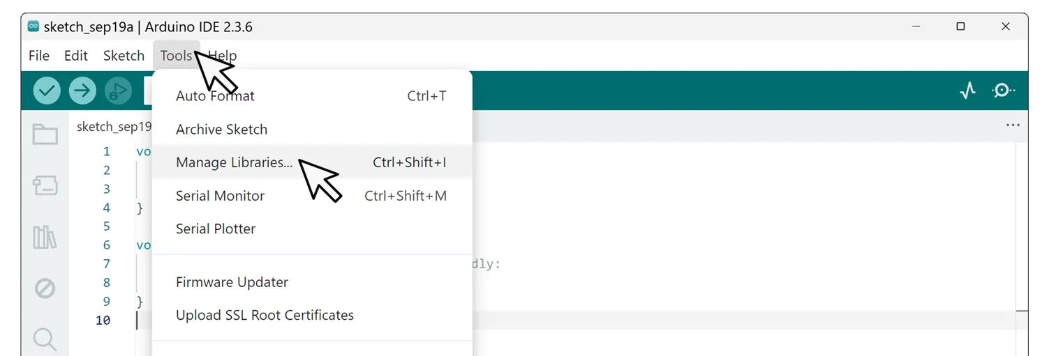
In the Arduino IDE: Tools → Manage Libraries…
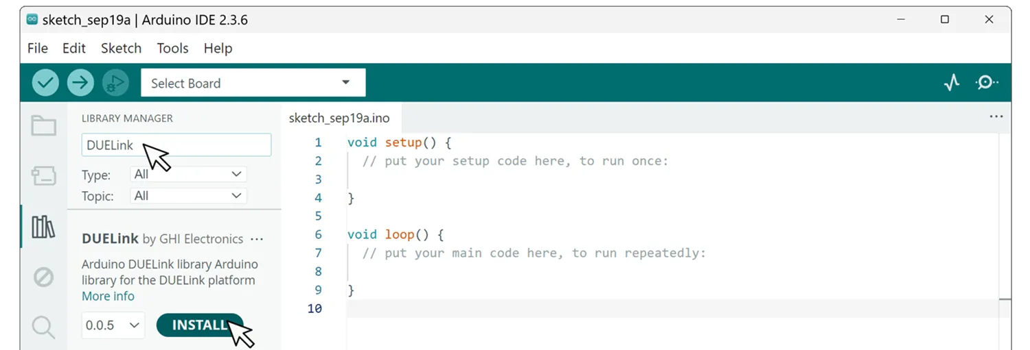
Search STM and install both DUELink and STM32 MCU based boards.
A first sketch
Two DUELink modules chained on the Downlink, here driven over UART (Serial2). Blink the STAT LED on each one.
#include <DUELink.h>

SerialTransport transport(Serial2);
DUELink duelink(transport);

void setup() {
  Serial2.begin(115200);
  duelink.Connect();

  duelink.Engine.Select(1);              // first module in chain
  duelink.System.StatLed(200, 200, 10);  // blink 10 times

  duelink.Engine.Select(2);              // second module
  duelink.System.StatLed(200, 200, 0);   // blink forever
}

void loop() {}
Same modules, same text commands — just emitted from an Arduino sketch instead of a PC.
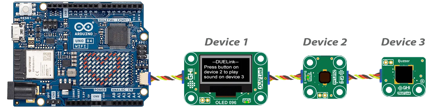
A more interactive sketch
UNO R4 WiFi with an OLED 0.96 display, a Button, and a Buzzer chained on I2C (Wire1). Pressing the button plays a tone.
#include "DUELink.h"

TwoWireTransport transport(Wire1);
DUELink duelink(transport);

void setup() {
  Serial.begin(9600);
  Wire1.begin();
  duelink.Connect();

  duelink.Engine.Select(1);                       // OLED 0.96
  duelink.Graphics.Clear(1);
  duelink.Graphics.Text("--DUELink--", 0, 10, 1);
  duelink.Graphics.Text("Press button on", 0, 1, 21);
  duelink.Graphics.Text("device 2 to play", 0, 1, 31);
  duelink.Graphics.Text("sound on device 3", 0, 1, 41);
  duelink.Graphics.Show();

  duelink.Engine.Select(2);                       // Button
  duelink.Button.Enable(1, 1, 1);
}

void loop() {
  delay(100);
  duelink.Engine.Select(2);
  if (duelink.Button.Up(1) == 1) {
    duelink.Engine.Select(3);                     // Buzzer
    duelink.Frequency.Write(7, 1000, 50, 0.5);
  }
}
Simple commands, complex behavior — possible because each module ships with the standard DUELink engine and the appropriate drivers.
Each module page in the catalog includes Arduino samples under Tethered Samples.
Going further
- Arduino IDE — load Arduino code onto a DUELink module itself
- Chain modules — how DUELink chains work, including third-party Qwiic/STEMMA on the same bus