Daisylink
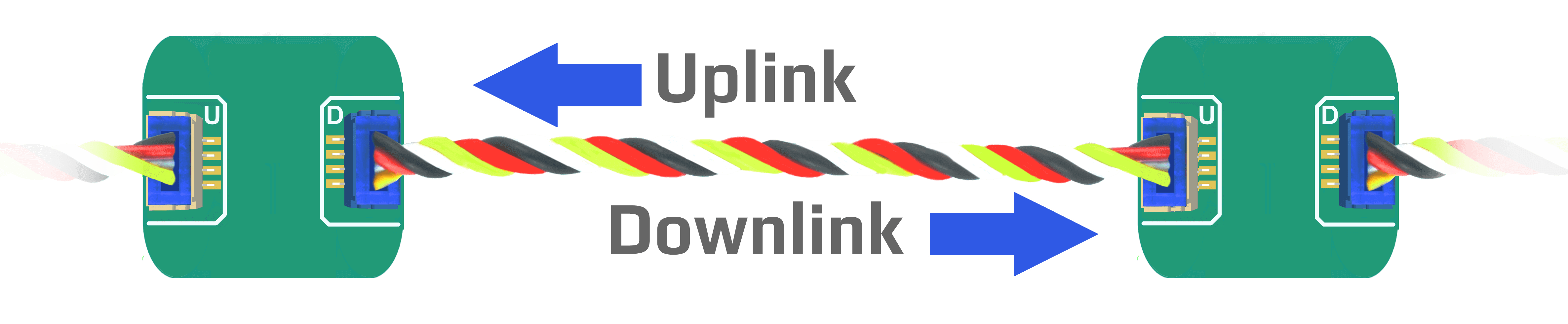
In a DUELink setup, where there are more than one module, there will always be a connection between the Uplink and Downlink sockets, creating a Daisylink. Each single module in a Daisylink is an active repeater of the signal. There will be no degradation of the signal quality. If necessary, add Power Inject to help in powering devices on its Downlink.
Device Selection
The Standard Library offers the Sel() command to activate devices on the chain. To blink the status LED on the second device on the Daisylink chain, use Sel(2) followed by StatLed(200,200,50). The LED will blink 50 times on the second module in the stream.
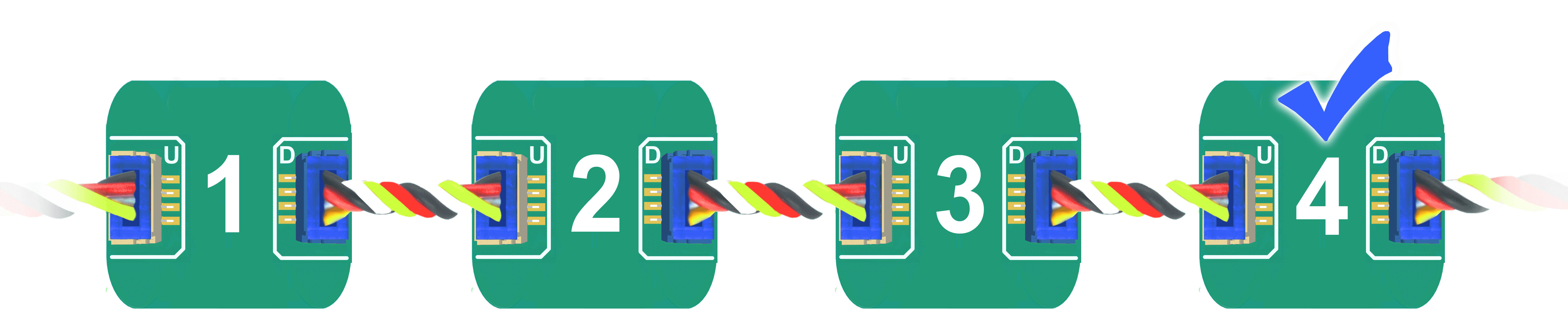
Daisylinked devices on a stream are addressed from 1. The fourth device on the bus is selected using 'Sel(4)'.
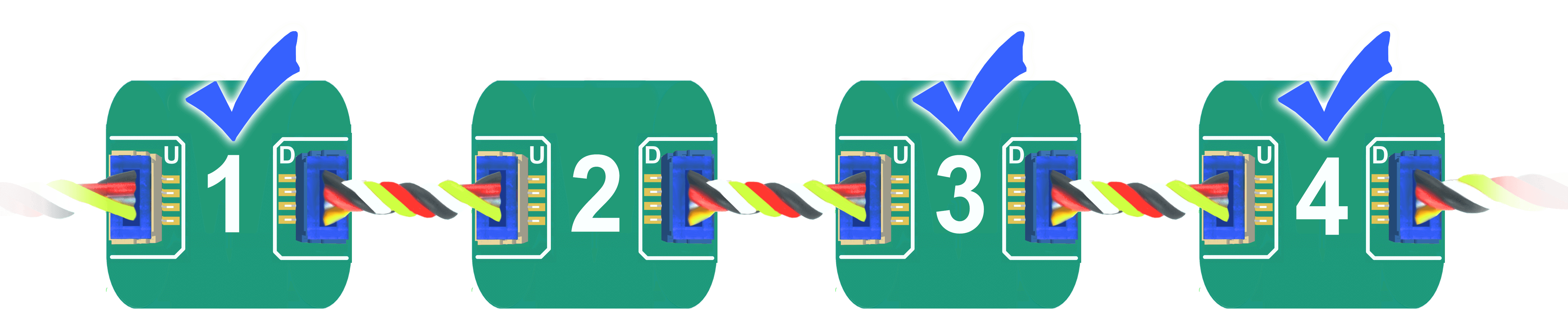
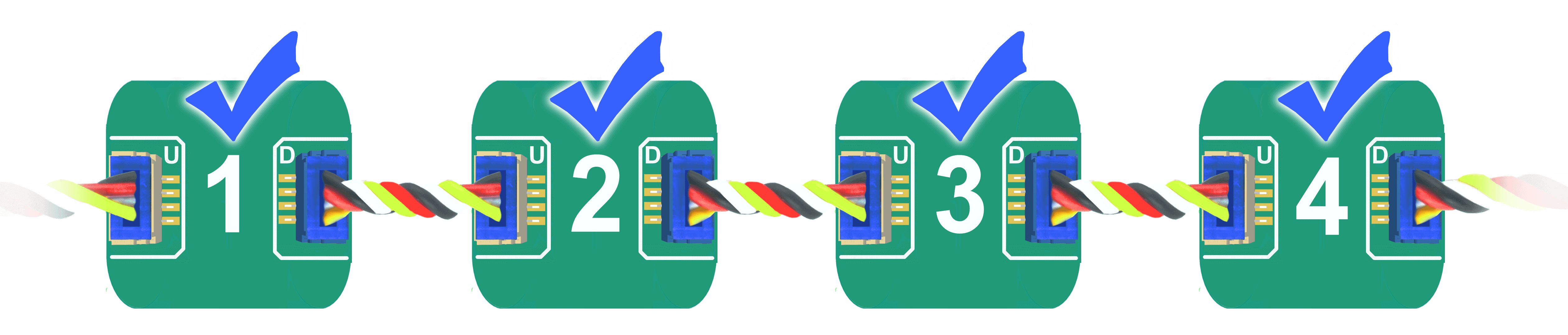
It is possible to select more than one device at once. Let's say we want to select devices 1,3 and 4 Sel(1,3,4)
Broadcast
Address zero is a special address on the chain, which indicates a broadcast selection. During a broadcast, all modules are required to process the command.
In this example, we have 4 modules connected.
Sending Sel(0) followed by StatLed(200,200,50) will blink the status LED 50 times on each one of the four modules. It is also possible to read from multiple devices. Sel(0):Print("Hi").
Device Addressing
When modules power up, they have a NULL interface, and they have no set address yet. Once an Interface is selected, such as USB, then the first device will set its own address to 1 and then command all Downlink devices to take a new address, 1, 2, 3, 4...etc.
To initiate the Daisylink and enumerate the modules connected on the Downlink interface, a command must be sent. This very first command is only seen by the first device. An empty command (just a carriage return) can also be used.
Only smart modules receive an address. For example, both power modules in this Daisylink do not have an address.
Use GetAddr() to read the current address. If the current address is zero, then the module has not been enumerated yet. There are 2 options for module to be enumerated, either by detecting an Interface or by configuring a module in host mode as explained below.
Since devices get enumerated in order, and each module needs 1ms to 2ms to be ready, commands should not be issues to modules for 2ms for each module in the Daisylink.
Host Mode
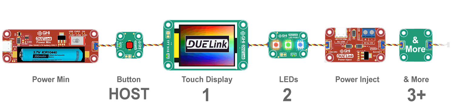
Typically, a host is used to command a stream of Daisylinked devices. There are several Supported Systems and many supported Languages.
DUELink modules can run Standalone and can also be the host of other Daisylinked modules, connected on the Downlink socket.
Devices automatically receive an address, starting with 1. Note how power modules do not count. They are just power sources.
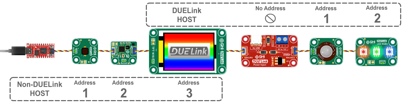
When a module is configured as a host, the host-module can be anywhere in the chain. Here is an example where the third module is configured as a host. Note how the host module is address 3 to its host, which is the Sparkfun micro. The other modules on its Downlink also have addresses starting at 1 but these are only visible to their host.
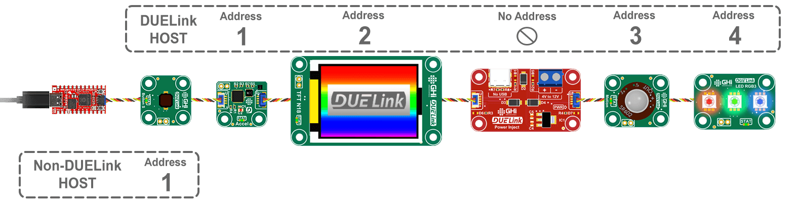
This host can also be anywhere else in the link, including the first device. Think of modules as always physically connected but logically separated and controlled by their own respective host.
As documented on the Downlink interface page, DLMode(2) command is used to switch the module to host mode. This will automatically reset and re-enumerate thats host's clients.
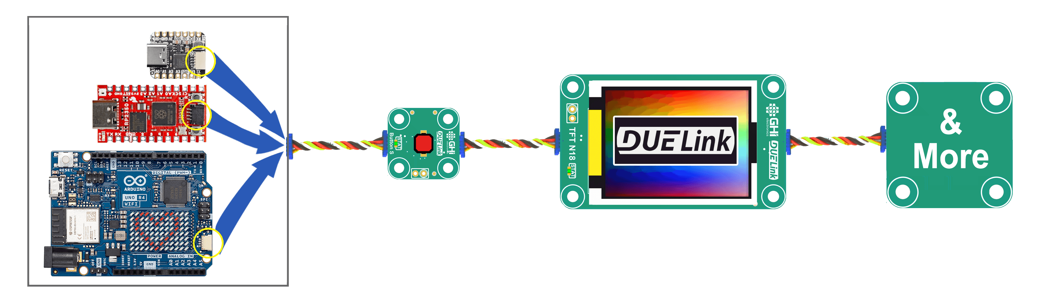
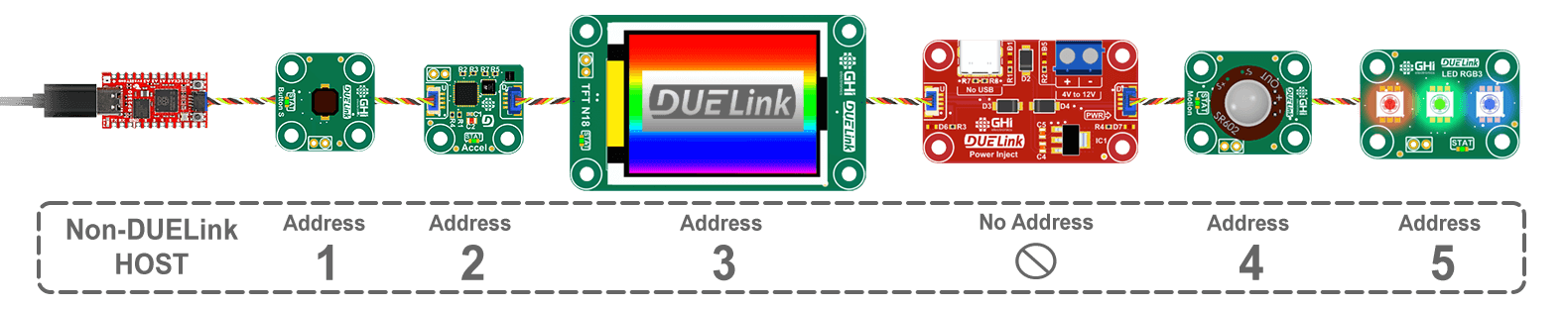
This is what addresses look like without a DUELink host. It still however has an external non-DUELink host.
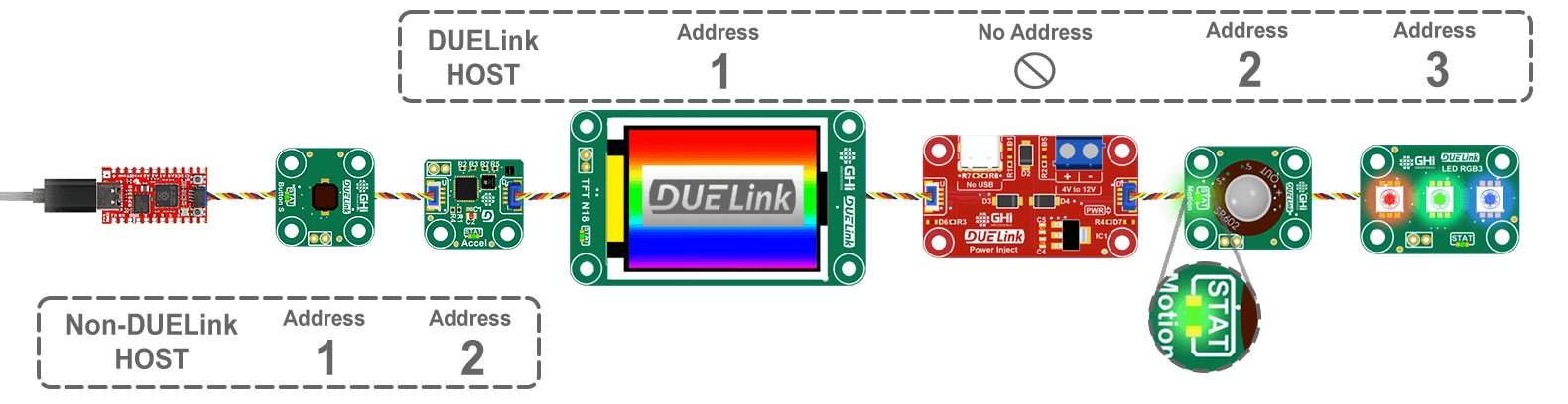
Load this code on the second device, which turns it into a host. It then sends a command to it's client address 2 to blink its status LED.
DLMode(2) # Switch Downlink to host mode
Wait(100) # This delay is more than enough for 50x modules.
Cmd("Sel(2)") # Select second device
Cmd("StatLed(200,200,50)") # Blink the LED 50 times on the selected device
Loading programs on devices other than first device is covered elsewhere. For simplicity, you can plug the device you want to program directly to a PC (using USB Hook for example), load it with your program, and then move it anywhere in the Daisylink.
This is what the link would look like.
A device in "host" mode is still listening to commands coming from Uplink, but it does not forward the commands Downlink. This allows for programming and configuring the host, from DUELink Console for example.
Gateway
In some cases, a specialized interface can be used to pipe data into Daisylink. For example, Wireless Hook opens up a gateway between Bluetooth and the connected modules. Just like in host, the module itself has its own address, however the module runs in a special mode where it is a host to the connected modules.
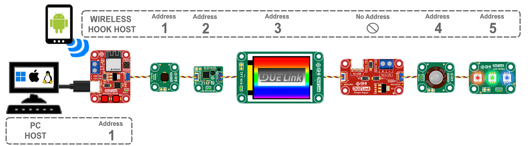
This example assumes the connection was established and only shows the connection part. The Wireless Hook page has the full drivers to establish the connection.
# Assuming a wireless connection was established
DLMode(3) # Switch Downlink to UART gateway mode
# Now any data coming from UART will go Downlink and and data coming from Downlink will go up UART.